NEWS
[ARTICLE] Why You Need To Review Your Technical Documentation NOW (And 8 Pitfalls to Avoid at all Costs)
According to the Medical Device Survey 2021 by The European Association for Medical devices of Notified Bodies, Medical Device (MD) companies who have applied for MD Regulation (MDR 2017/754) certification remain a minority (only 26.3% had applied at the end of 2021). A lot of applications are yet to be received!
Bottleneck for Technical Documentation (TD) review by Notified Bodies (NB) is a reality
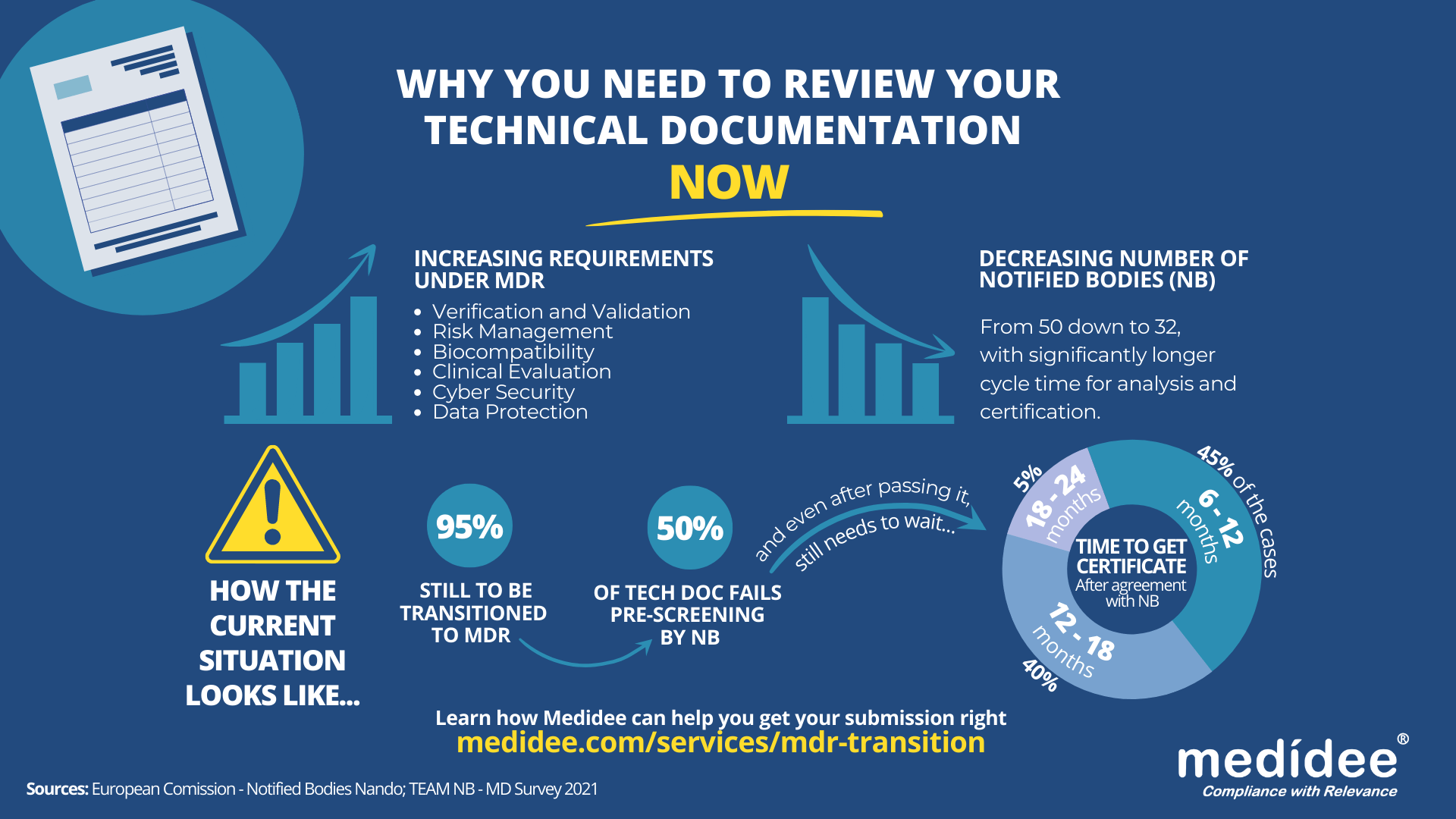
With increased requirements to comply with MDR and a decreased number of Notified Bodies being able to deliver certificates under those regulations (from 50 down to 32 as of August 1st), it gets longer and longer to obtain a certification.
Currently, from the positive outcome of the Completeness Check, it takes between 6 (low-risk devices) and 24 months (high risk)until the issuance of the MDR certificate. Knowing that certificates issued under the MDD/AIMDD remain valid until May 2024 at the latest, waiting too long before submitting your Technical Documentation can result in having no valid certificate to operate in the market.
How to speed up the certification process: be right the first time!
The requirements under MDR are more stringent compared to previous directives. A thorough gap analysis of your Technical Documentation needs to be performed at first to identify the (possibly) missing documents to demonstrate compliance against all General Safety and Performance Requirements (GSPR). Additional device testing might also be required which will significantly delay the moment of application to a NB.
Indeed, with the implementation of the Completeness Check process, at least 50% of the TD submitted are deemed incomplete, and NB request additional information to start the assessment according to the Medical Device Survey 2021. These numbers are confirmed by two other surveys published very recently by the European Commission and MedTech Europe.
Considering these timelines, you cannot afford to wait for the initial feedback from the Notified Body to discover deficiencies in your Technical Documentation – you really need to be right the first time, avoiding common pitfalls.
8 Technical Documentation pitfalls to avoid at all costs
Having performed many gap analyses regarding TD compliance against MDR, as well as having accompanied several companies through MDR transition, Medidee has a clear vision of the main pitfalls throughout this process. Below are typical examples of which companies should be aware before submission. If you would like to learn more about this topic, don't miss the chance to watch our on-demand webinar:

Pitfall 1: Your TD is not well organized
A clear structure throughout the technical documentation is helpful in ensuring that the reviewing body can clearly understand the contents. The MDR now provides, in Annexes II and III, detailed instructions on what is the minimum content of technical documentation, also defining a specific structure for it.
Pitfall 2: No identifiable thread within your TD
Manufacturers shall maintain traceability from the User Requirements Specification (URS) to the Functional Requirements Specification (FRS), risk analysis, clinical evaluation and the GSPR. This is key to demonstrating full compliance to GSPR.
Pitfall 3: Negligence of Post Market Surveillance data
Manufacturers of devices, even those that have been on the market for many years, need to collect or complete a review of existing Post-Market Surveillance (PMS) data, to be able to cover the requirements related to clinical evaluation, as set out by Article 61 of the MDR. For devices that have previously been placed on the market, this includes, but is not limited to the Post Market Clinical Follow Up (PMCF) data, vigilance data, user feedback and complaints.
Pitfall 4: No anticipation of risk class changes for your device
Although this applies to all MDs, it is particularly true for Software as Medical Device (SaMD). Indeed, the classification rule 11 from MDR, and related MDCG guideline MDCG 2019-11, lead to a class upgrade: 80% of the SaMD which did not need a NB before MDR implementation do require one now. This leads to a tremendous change in the company’s organization to obtain a certificate, while also adding to the above-mentioned bottleneck effect.
Pitfall 5: Not enough precision on how GSPR compliance is reached
Manufacturers must provide suitable objective evidence to show that their device satisfies the requirements detailed in Annex I of the MDR GSPRs. Where manufacturers determine that specific GSPRs are not applicable to their device, “an explanation as to why [they] do not apply” must be provided, which is a new requirement in the MDR (Annex II, point 4(a)). Moreover, pointing precisely to the key documents demonstrating compliance to each GSPR will simplify the TD review by the NB as well as help you identify possible gaps within your own TD before submission.
Pitfall 6: No implementation readiness documentation of the UDI traceability system
The Unique Device Identification (UDI) system has a direct impact on the labelling, artwork, and DoC, as manufacturers will need to place a UDI carrier on the label of the device and on all higher levels of packaging, except the shipment packaging (Article 27, point 4). Your quality management system will also need to be aligned to the UDI system implementation. Beware to anticipate any risk linked to the UDI system implementation within your Risk Management file.
Pitfall 7: Absence of specific information relating to device design and history
For all classes of medical devices, manufacturers must now provide, as per Annex II, information in the technical documentation to explain the design stages and procedures that are applied to their device (Annex II, point 3). Under the requirements of the MDD/AIMDD, this was only the case for class III devices. Therefore, depending on the classification of the device, manufacturers may need to update the content of the technical documentation.
Pitfall 8: Person Responsible for Regulatory Compliance (PRRC) not designated early enough within your organization
Article 15 of the MDR clearly stipulates the obligation for medical device manufacturers to have available, within their organization (or permanently and continuously at their disposal for micro and small companies), at least one person, possessing the necessary expertise in the field of medical devices, who is responsible for regulatory compliance. Among other responsibilities, the person or people responsible for regulatory compliance must ensure that the technical documentation is compiled and maintained.
Medidee: Easying your MDR transition with services tailored to your needs
From a simple gap analysis to guide you towards the appropriate tests or data reviews needed, to performing those reviews, building test protocols, writing test reports or consolidating the entire TD, Medidee’s team of experts is ready to support you in this process.
Having accompanied many companies in the transition to MDR, Medidee has gained experience and is able to make this transition as smooth as possible for your organization.
Do not wait any longer! Learn more about our MDR Transition service and contact us today to kick-start your own MDR transition!
This article was written by Dr Lydie Moreau.

[ARTICLE] IVD Manufacturers’ New Year’s Resolutions: 6 Reasons to Start the Performance Evaluation of your Device Now
Once a device is used for diagnostic purposes on human specimens, the European Union expects, in accordance with Article 5(3) of Regulation (EU) 2017/746 (IVDR), a performance evaluation of the device as a demonstration of compliance with the relevant General Safety and Performance Requirements (GSPRs) and this regardless of the device’s risk class.
As defined within Article 2(44) of the IVDR this means an “assessment and analysis of data to establish or verify the scientific validity, the analytical and, where applicable, the clinical performance of a device”.
The performance evaluation shall be based on a continuous process and follow a defined and methodologically sound procedure, based on an established device-specific plan, i.e., the Performance Evaluation Plan (PEP). The identified performance and safety data, which shall allow to demonstrate compliance with relevant GSPRs related to the device’s performance characteristics, is then consolidated in the Performance Evaluation Report (PER). The PER is a part of the device’s technical documentation and shall be reviewed by the Notified Body during the conformity assessment procedure. De facto, manufacturers of legacy IVD devices will need to invest resources in evaluating the performance of their devices prior to their transition to IVDR.
Here are 6 reasons why manufacturers should not put off this endeavor and start the process now
1. It ensures alignment with the current "state of the art"
In accordance with the requirements of the Regulation (Annex XIII), a PEP must include “a description of the state of the art, including an identification of existing relevant standards, Common Specifications, guidance or best practices documents”. Implementing the PEP as soon as possible will ensure that the device is still aligned with the current state of the art and does not require major design improvements or additional testing according to the latest guidelines. This is especially important because “the performance evaluation of an IVD must consider the benefit-risk ratio in light of the state-of-the-art” and as further stipulated in MDCG 2022-2, “risks for IVDs are often generated from a series of events which may involve several factors such as inadequate design characteristics as well as immature technology”. Therefore, establishing the state of the art is the first step in the preparation of the performance evaluation. As it involves a systematic and methodological approach to the literature review, it requires time and resources.
2. It allows for an early assessment of the level of clinical evidence required
The level of clinical evidence needed to fully demonstrate the performance and safety of the device as claimed by the manufacturer will depend on the characteristics of the device and its intended use. Manufacturers transitioning their devices to IVDR shall assess as soon as possible the level of clinical evidence required. This includes verifying that all performance and safety claims, including those used for marketing purposes, are supported by an adequate level of evidence. Doing so will either allow for timely follow-up actions to collect additional performance data in case some claims are not yet sufficiently supported by clinical evidence, or to reword the device’s intended use taking into consideration the existing clinical evidence.
3. It helps to identify and react to gaps in the analytical performance
Conducting a performance evaluation in advance will allow the manufacturer to identify gaps in the data supporting the analytical performance of the device in a timely manner. If gaps are identified, the manufacturer will be able to generate new evidence in accordance with common specifications, guidelines, or applicable standards, to demonstrate that the IVD in question is capable of reliably, accurately, and consistently detecting the analyte, and thus GSPRSs linked to the analytical features of the device are adequately addressed.
4. It determines if sufficient clinical performance data is available
It is also important to promptly determine whether sufficient clinical performance data is available to support the device's intended use, as well as the claimed indications. The level of clinical evidence should be consistent with the clinical strategy defined in the PEP. As per MDCG 2022-2 “the manufacturer should demonstrate that the IVD has been tested for the intended use(s), target population(s), use condition(s), operating- and use environment(s) and with all the intended user group(s)”. This last aspect is particularly important when it comes to devices intended for point-of-care testing, where manufacturers need to ensure that the clinical data reflects the device’s use environment. Available clinical data may come from the manufacturer’s own clinical performance studies, Post-Market Surveillance (PMS) or peer-reviewed literature. Identifying gaps in advance will allow time to plan and eventually conduct a clinical performance study in compliance with IVDR and ISO 20916:2019, if necessary. It is important to remember that under Article 56(4) of the IVDR, “Clinical performance studies in accordance with Section 2 of Part A of Annex XIII shall be carried out unless it is duly justified to rely on other sources of clinical performance data”.
5. It supports risk identification and management
MDCG 2022-2 (6.2) states that “the risk management system should be carefully aligned with and reflected in the performance evaluation process of the IVD, considering the clinical risks to be addressed as part of the performance evaluation, performance studies, and post-market performance follow-up(s)”. Hence, manufacturers must ensure that all risks identified through the performance evaluation process are adequately addressed within the device’s risk management documents. Timely completion of the performance evaluation will allow the manufacturer sufficient time to address newly identified risks, if necessary.
6. It facilitates robust Post-Market Surveillance and Performance plans
In the event that the time frame is still too short to address all identified performance gaps through appropriate V&V testing or clinical performance studies, the manufacturer will be able to work on a robust PMS and Post-Market Performance Follow-up (PMPF) plan aligned with the performance evaluation outcome. Additionally, in case new PMS and PMPF data were collected after the initial performance evaluation, the PEP and PER should be updated in light of this new data prior to the device’s conformity assessment. As this always requires a certain amount of time for proper implementation, it is best to plan ahead.
In conclusion, the performance evaluation may identify some gaps in the quantity or quality of available clinical evidence or in the completeness of the device’s risk management documentation or PMS/PMPF plan. Depending on the extent and nature of these gaps, it may take time to address them, especially if a clinical performance study is needed, which may require months or years. Additionally, manufacturers should keep in mind that a conformity assessment procedure can take 18-24 months, which means that for legacy IVD devices classified as Class D or C according to IVDR, compliance with GDPR is expected by May 26, 2025 and 2026, respectively.
With this in mind, we advise you to place the performance evaluation of your device as a top priority on your to-do list for 2023. Contact Medidee today to discuss your needs and how Medidee supports you in addressing them: www.medidee.com/contacts
Don't miss any of our upcoming IVD content! Follow Medidee on LinkedIn
This article was written by Dr. Julianne Bobela.
[ARTICLE] Electrical Safety: How changes to IEC 60601 Series trigger additional testing for your device (IEC 60601-1, Edition 3.2)
This article is the first one of a series about IEC 60601. It contains insightful information about IEC 60601-1 Edition 3.2, with a similar structure as the second article.
The latest amendment of IEC 60601-1 for medical electrical equipment - Part 1: General requirements for basic safety and essential performance (IEC 60601-1 Edition 3.2) was published on 2020-08-20 by the International Electrotechnical Commission (IEC). Edition 3.2 notably addresses issues raised by national committees and questions submitted to IEC/SC 62A/Working Group 14 with regards to previous version 3.1.
Since the 30th of May 2022, the United States Food & Drug Administration (FDA) has listed IEC 60601-1 3.2 Edition for Medical Electrical Equipment – Part 1: General requirements for basic safety and essential performance as a recognized standard (FDA recognition number 19-46). IEC 60601-1 3.2 Edition will replace the current listed IEC 60601-1 3.1 Edition (FDA recognition number 19-4) by the 17th of December 2023. Until this date, FDA will accept declarations of conformity referring to IEC 60601-1 3.1 Edition, in support of premarket submissions.
To date, no announcement relative to an official transition period for the applicability of Edition 3.2 or to its harmonization under the Medical Device Directive (93/42/EEC) or Medical Device Regulation (EU 2017/745) has been issued in the official journal of the European Union. As per the list of recognized consensus standards of the Food & Drug Administration (FDA), ES60601-1:2005/(R)2012 and A1:2012, C1:2009/(R)2012 and A2:2010/(R)2012 (Consolidated Text) are currently listed.
In the absence of any official communication within the European Union on the matter, it is anticipated that manufacturers will be granted a transition period of 3 to 4 years after the date of publication, before they will be expected to demonstrate compliance with the applicable new requirements introduced by the amended standard.
Medidee has observed that manufacturers of electrically driven active medical devices are commonly unaware of the latest revision of this standard and consequently of the new requirements it entails. This article aims to raise awareness of this amendment of IEC 60601-1, to summarize the main changes compared to the previous version of the standard, and to illustrate through a few examples how these changes may affect manufacturers of medical electrical equipment and systems.
What are main the differences between IEC 60601-1 Edition 3.1 and Edition 3.2?
The main clauses affected in IEC 60601-1 Edition 3.2 are:
Clause 2 normative references
Clause 3 terminology and definitions
Clause 7 identification and marking
Clause 8 protection against electrical hazards
Clause 11 protection against excessive temperatures and other hazards
Clause 13 hazardous situations and fault conditions
Clause 14 programmable electrical medical systems (PEMS)
Importantly, the normative references of the standard have also been updated in Edition 3.2. The changes to referenced standards are shown in bold text below:
IEC 60065:2001+AMD1:2005+AMD2:2010 Audio, video and similar electronic apparatus
IEC 60068-2-2:2007 Environmental testing
IEC 60227-1:2007 Insulated cables
IEC 60245-1:2003+AMD1:2007 Rubber insulated cables – general requirements
IEC 60335-1:2010 Household and similar appliances
IEC 60417 Graphical symbols for use on equipment
IEC 60601-1-2:2014+AMD1:2020 Electromagnetic disturbances – requirements and tests
IEC 60601-1-3:2008+AMD1:2013 Radiation protection in diagnostic X-ray equipment
IEC 60601-1-6:2010+AMD1:2013+AMD2:2020 Usability
IEC 60601-1-8:2006+AMD1:2012+AMD2:2020 Alarm systems in medical electrical equipment
IEC 60664-1:2007 Insulation coordination
IEC 60730-1:2014 Automatic electrical controls for household and similar use
IEC 60747-5-5:2007 Semiconductor devices – optoelectronic devices - photocouplers
IEC 60825-1:2014 Safety of laser products
IEC 60065:2001+AMD1:2005+AMD2:2010 Audio, video and similar electronic apparatus IEC 60068-2-2:2007 Environmental testing
IEC 60227-1:2007 Insulated cables
IEC 60245-1:2003+AMD1:2007 Rubber insulated cables – general requirements
IEC 60335-1:2010 Household and similar appliances
IEC 60417 Graphical symbols for use on equipment
IEC 60601-1-2:2014+AMD1:2020 Electromagnetic disturbances – requirements and tests IEC 60601-1-3:2008+AMD1:2013 Radiation protection in diagnostic X-ray equipment
IEC 60601-1-6:2010+AMD1:2013+AMD2:2020 Usability
IEC 60601-1-8:2006+AMD1:2012+AMD2:2020 Alarm systems in medical electrical equipment
IEC 60664-1:2007 Insulation coordination
IEC 60730-1:2014 Automatic electrical controls for household and similar use
IEC 60747-5-5:2007 Semiconductor devices – optoelectronic devices - photocouplers
IEC 60825-1:2014 Safety of laser products
IEC 60851-3:2009 Winding wires – test methods mechanical properties
IEC 60851-5:2008 Winding wires – test methods electrical properties
IEC 60950-1:2005+AMD1:2009+AMD2:2013 Information technology equipment
IEC 61058-1:2000+AMD1:2001+AMD2:2007 Switches for appliances
IEC 62133 Secondary cells and batteries
IEC 62133-2 Secondary cells and batteries (Lithium systems)
IEC 62304:2006+AMD1:2015 Medical device software – software life cycle processes
IEC 62368-1:2018 Audio/ video, information, and communication technology equipment
ISO 7010:2019 Graphical symbols
ISO 11135-1:2007 Sterilization of health care products – Ethylene oxide
ISO 11137-1:2006 Sterilization of health care products – requirements for validation
ISO 13857:2008 Safety of machinery
ISO 14971:2019 Medical devices – application of risk management
ISO 15223-1:2016 Medical devices – symbols used with medical device labels
ISO 17665-1:2006 Sterilization of health care products – requirements for validation (moist heat)
ISO 80000-1:2009 Quantities and units
What do these changes mean in practice?
Due to the technological progress and resulting technical changes, the standards to ensure a safe and effective medical device needs to develop too (state of the art). To comply with IEC 60601-1 3.2 edition the latest editions of applicable process, particular, collateral, and component standards need to be considered by the medical device applicant.
Medical device manufacturers are advised to take advantage of the transition period to perform a gap analysis of their technical documentation (TD) against Edition 3.2 and update their documentation accordingly. Once potential gaps have been cleared, a new test report according to IEC 60601-1:2005+AMD1:2012+AMD2:2020 Edition 3.2 can be requested from an external ISO/IEC 17025 accredited testing laboratory. If the current IEC 60601-1 test report uses CB-Scheme as test scheme, it should be kept in mind that according to IEC Operational Document OD-2037 clause 3.1, a new Certification Body (CB) test certificate shall be issued with a new CB test certificate number. Thanks to the fact that now the TD will have been revised to comply with technical state of the art, a smooth certification process will be assured.
Let's focus on the changes to IEC 60601-1 clause 8 - protection against electrical hazards and clause 14 - programmable electrical medical systems. One noticeable change to clause 8 concerns the introduction of the requirement to measure the voltage of all accessible conductive parts of the Signal Input/ Signal Output (SIP/SOP) or power output connectors to earth for medical electrical equipment which is equipped with SIP/SOP connectors or separate power supply output connectors. Depending on whether the voltage is greater than 60Vdc or 42,4Vac - touch current measurement according to clause 8.7.3 will need to be conducted. For measuring the voltage of the SIP/SOP, please refer to the below-mentioned electrical schematic.

Another noteworthy update of IEC 60601-1 Edition 3.2 affecting clause 8 is the addition of the normative reference to the standard IEC 60747-5-5:2007 Semiconductor devices – optoelectronic devices – photocouplers. Optocouplers which comply with IEC 60747-5-5:2007 or a later edition are considered equivalent to the requirements of 8.8.2 for distances through solid insulation and 8.9.3 for spaces filled by insulation compound. If your medical electrical device or system uses an optocoupler as a solid insulation forming a means of operator protection, the following verification measures apply and need to be conducted:
Air clearance at the outside of the opto-coupler
Creepage distance at the outside of the opto-coupler
Dielectric strength across the opto-coupler
Moreover, Clause 14 Programmable Electrical Medical Systems (PEMS) introduced a direct reference to IEC 62304:2006+AMD1:2015 Medical device software – software life cycle processes. Please keep in mind that the requirements in subclauses 14.2 to 14.12 shall apply to PEMS if the medical electrical equipment uses Programmable Electronics Subsystem (PESS) to provide functionality necessary for basic safety or essential performance or if the application of risk management as described in 4.2 shows that the failure of any PESS leads to an unacceptable risk. Medical device manufacturers are required to evaluate if clause 14 of IEC 60601-1 - and therefore specific clauses of IEC 62304 - are applicable.
How can Medidee support your company?
Our team of electrical safety specialists at Medidee assist you in identifying all areas requiring updates to meet the new requirements introduced by IEC 60601-1 Edition 3.2 through a detailed review of the technical documentation of your medical electrical device or system, as well as provide support in the implementation of applicable new IEC 60601-1 Edition 3.2 requirements. For instance, Medidee reviews and updates the list of critical components and insulation diagram, and process referenced standard-related changes incurred by the update of referenced standards ISO 14971:2019, IEC 62304:2006+AMD1:2015, and IEC 60601-1-6:2010+AMD1:2013+AMD2:2020/ IEC 62366-1:2015+AMD1:2020.
In addition, Medidee supports you in communicating with external accredited testing laboratories and notified bodies, to ensure a smooth certification process of the medical electrical equipment or system.
Contact Medidee today to discuss your needs and how Medidee supports you in addressing them: www.medidee.com/contacts
This article was written by Stefan Staltmayr.

[ARTICLE] Electromagnetic Compatibility: How changes to IEC 60601 Series trigger additional testing for your device (IEC 60601-1-2, Edition 4.1)
This article is the second one of a series about IEC 60601. It contains insightful information about amendment 1 of IEC 60601-1-2, following a similar structure as the first article.
The latest amendment 1 of IEC 60601-1-2 for Medical electrical equipment - Part 1-2: General requirements for basic safety and essential performance - Collateral Standard: Electromagnetic disturbances - Requirements and tests (IEC 60601-1-2 Edition 4.1) was published on 2020-09-01 by the International Electrotechnical Commission (IEC). Edition 4.1 notably addresses issues raised by national committees and questions submitted to IEC/SC 62A with regard to previous version 4.0.
Since the 21st of December 2020, the United States Food & Drug Administration (FDA) has listed IEC 60601-1-2 4.1 Edition Medical electrical equipment - Part 1-2: General requirements for basic safety and essential performance - Collateral Standard: Electromagnetic disturbances - Requirements and tests as a recognized standard (FDA recognition number 19-36). IEC 60601-1-2 4.1 Edition will replace the current listed IEC 60601-1-2 4th Edition (FDA recognition number 19-8) by the 17th of December 2023. Until this date, FDA will accept declarations of conformity referring to IEC 60601-1-2 4th Edition, in support of the premarket submission.
To date, no announcement relative to an official transition period for the applicability of Edition 4.1 or to its harmonization under the Medical Device Directive (93/42/EEC) or Medical Device Regulation (EU 2017/745) has been issued in the official journal of the European Union.
In the absence of any official communication within the European Union on the matter, it is anticipated that manufacturers will be granted a transition period of 3 to 4 years after the date of publication before they will be expected to demonstrate compliance with the applicable new requirements introduced by the amended standard.
WHAT ARE THE MAIN DIFFERENCES BETWEEN CURRENT IEC 60601-1-2 EDITION 4.0 AND EDITION 4.1?
Clauses affected in IEC 60601-1-2 Edition 4.1 compared to 4.0 Edition are:
Clause 2 Normative references
Clause 3 Terms and definitions
Clause 4.3.3 Power input voltages and frequencies Table 1 – Power input voltages and frequencies during the tests
Clause 7.1.12 Permanently installed large ME equipment and large ME systems
Clause 7.3 Emissions requirements summary Table 2 – Emission limits per environment
Clause 8.1 Electromagnetic immunity requirements for ME equipment and ME systems - general
Clause 8.6 Permanently installed large ME equipment and large ME systems
Clause 8.9 Immunity test levels
Clause 8.11 Immunity to proximity magnetic fields in the frequency range 9kHz to 13,56 MHz
Figure 3 – Examples of locations within EM environments
Table 4 – Enclosure Port
Table 5 – Input a.c. power port (1 of 2 and 2 of 2)
Table 8 – SIP/SOP port
Table 9 – Test specifications for enclosure port immunity to RF wireless communications equipment
Table 10 – minimum test report contents (2 of 2)
Table 11 – Test specifications for enclosure port immunity to proximity magnetic fields
Table A.3 – Test specifications for enclosure port immunity to RF wireless communications equipment
Annex A.1 Safety and performance
Subclause 4.2 – Non-ME equipment used in an ME system
Subclause 4.3.3 – Power input voltages and frequencies
Subclause 5.2.2.1 a), Compliance with each emission and immunity standard
Subclause 7.1.12 – Permanently installed large ME equipment and Large ME systems
Subclause 8.6 – Permanently installed large ME equipment and large ME systems
Subclause 8.9 – Immunity test levels b) Environments
Subclause 8.9 – Immunity test levels c) Immunity test level determination
Subclause 8.10 – Immunity to proximity fields from RF wireless communications equipment
Subclause 8.11 – Immunity to proximity magnetic fields in the frequency range 9 kHz to 13,56 MHz
Annex F Guidance on the application of risk management with regard to electromagnetic disturbances in this collateral standard
Figure F.1 – Risk management flow in IEC 60601-1-2
Table G.1 Recommended minimum test plan contents (2 of 2)
Importantly, the normative references of the standard have also been updated in Edition 4.1. The changes to referenced standards are shown in bold text below:
IEC 60601-1:2005+AMD1:2012+AMD2:2020
IEC 60601-1-8:2006+AMD1:2012+AMD2:2020
IEC 60601-1-11:2015+AMD1:2020
IEC 60601-1-12:2014+AMD1:2020
IEC 61000-4-5:2014+AMD1:2017
IEC 61000-4-11:2004+AMD1:2017
IEC 61000-4-39:2017
CISPR 11:2015+AMD1:2016+AMD2:2019
CISPR 14-1:2016
CISPR 16-1-2:2014+AMD1:2017
CISPR 32:2015
ISO 14971:2019
WHAT DO THESE CHANGES MEAN IN PRACTICE?
Due to technological progress and resulting technical changes, the standards to ensure a safe and effective medical device need to develop too (state of the art). To comply with IEC 60601-1-2 4.1 edition, the latest editions of applicable process, particular, collateral, and component standards need to be considered by the medical device applicant.
Medical device manufacturers are advised to take advantage of the transition period to perform a gap analysis of their technical documentation (TD) against Edition 4.1 and update their documentation accordingly. Once potential gaps have been cleared, a new test report according to IEC 60601-1-2:2014+AMD1:2020 Edition 4.1 can be requested from an external ISO/IEC 17025 accredited testing laboratory. If the current IEC 60601-1-2 test report uses CB-Scheme as test scheme, it should be kept in mind that according to IEC Operational Document OD-2037 clause 3.1, a new Certification Body (CB) test certificate shall be issued with a new CB test certificate number. Thanks to the fact that now the TD will have been revised to comply with technical state of the art, a smooth certification process will be assured.
Let´s focus on the introduction to IEC 60601-1-2 clause 8.11 – immunity to proximity magnetic fields in the frequency range 9 kHz to 13,56 MHz.
Subclause 8.11 explains why this requirement has been added. Due to a wide variety of sources with radiated fields in professional healthcare facility environments and home healthcare environments, concerns about risks have been raised. Many medical electrical equipments contain electronic components and circuitry which might be sensitive to radiated magnetic fields (source: Cf. IEC 60601-1-2 Edition 4.1 Subclause 8.11). Figure A.3 – Steps for evaluation of immunity to proximity magnetic fields provides a great overview if testing in accordance with Table 11 of IEC 60601-1-2 4.1 Edition is applicable. IEC 61000-4-39 electromagnetic compatibility – part 4-39: Testing and measurement techniques – radiated fields in close proximity – immunity test, describe the test and measurement condition.
Another noteworthy update of IEC 60601-1-2 Edition 4.1 affects clause 4.3.3 power input voltage and frequencies. Table 1 of clause 4.3.3 specifies the power input voltages and frequencies during testing. For instance, conducted disturbances (conducted emissions) according to CISPR11:2015+AMD1:2016+AMD2:2019 specifies the power input voltage for minimum and maximum rated voltage, if the difference between the maximum and the minimum rated input voltage is greater than 25% of the highest rated input voltage. Meaning, if your medical electrical equipment has a wide range input voltage supply of 100Vac – 240Vac, the difference of maximum and minimum rated input voltage is 140Vac, which is greater than 25% of highest rated input voltage (240Vac*25% = 60Vac), therefore the test needs to be conducted at minimum and maximum rated input voltage.
Previous IEC 60601-1-2 Edition 4.0 specified this test according to CISPR11 at any one voltage.
How can Medidee support your company?
Medidee has a dedicated team of electrical safety specialists who assist you in identifying all areas requiring updates to meet the new requirements introduced by IEC 60601-1-2 Edition 4.1, through a detailed review of the technical documentation of your medical electrical device or system, as well as provide support in the implementation of applicable new IEC 60601-1-2 Edition 4.1 requirements and sub-standards like CISPR 11 or IEC 61000-4-39. For instance, Medidee reviews and updates the technical documentation according to the updated standards to comply with IEC 60601-1-2 Edition 4.1. Furthermore, Medidee updates the test plan which is required as input for external test labs.
In addition, Medidee supports you in communicating with external accredited testing laboratories and notified bodies, to ensure a smooth certification process of your medical electrical equipment or system.
Contact Medidee today to discuss your needs and how Medidee supports you in addressing them: www.medidee.com/contacts
This article was written by Stefan Staltmayr.
[ARTICLE] Sampling Strategy: 10 FAQs on Sample Size Selection
Whether you are in the feasibility stage, verifying your design inputs and outputs, or validating your manufacturing process, choosing the wrong sample size for your tests can have a significant impact on your project, especially when this is detected during the market approval phase. Not only will it impact your time-to-market, but you will also likely find yourself repeating expensive testing, or worse, redesigning your product or process if you discover that adequate reliability is in fact not achieved.
Besides the benefits to your product development, sample size selection – including written justification – is also a regulatory requirement. Perhaps the most straightforward regulation is that from the FDA, found in the Quality System Regulation, 21 CFR §820.250(b), which states:
“Sampling plans, when used, shall be written and based on a valid statistical rationale. Each manufacturer shall establish and maintain procedures to ensure that sampling methods are adequate for their intended use... These activities shall be documented.”
Similarly, ISO 13458:2016 §7.3.6 and 7.3.7 state:
“The organization shall document verification … [and] validation plans that include methods, acceptance criteria and, as appropriate, statistical techniques with rationale for sample size.” These are clear requirements to include a written sample size justification in your testing protocols.
While the newly updated EU regulations (MDR/IVDR) do not carry explicit requirements like those of the FDA and in ISO 13485:2016, there is an implied requirement to provide a justification of your sample size selection through the requirements to show compliance with harmonized standards, found throughout the regulations. This includes ISO 13485:2016 in a very broad manner, but can also apply to topic-specific standards, such as those for sterilization or biocompatibility.
It is never too early in your project to start planning for sample size selection, considering its impact on your timelines, the cost of tests or the quality and quantity of representative devices to be produced to that end.
Here are 10 commonly asked questions we get when supporting clients with their sampling strategy.
1. Can’t I just use a sample size of 30 all the time?
First and foremost, the sample size you select should give you the information you need. Are you conducting an early feasibility test to inform your product design? Are you conducting design validation on a frozen design? These are very different types of tests which can require different sampling strategies. To get the most out of your testing – which can be costly to repeat – make sure to select an appropriate sample size to get the information you need. While n=30 may work for some tests, it will not always be the best sample size to meet your needs.
Besides type test (a test on one representative sample of the device with the objective of determining if the device, as designed and manufactured, can meet its requirements), some product-specific standards may include predefined sample size. In all the other cases, a statistical rationale shall be developed.
2. What exactly is a Confidence Level?
How do you know if your test results are meaningful? Choosing a sample size which is too small can leave the story of your testing incomplete – like trying to see the finished image of a puzzle without all the pieces in place. You can think of your confidence level like a 100-piece puzzle: how many pieces of the puzzle do you need to correctly guess the image? The more pieces you have, the more sure you can be about what the image is. The same is true for confidence level – a higher percentage will give you greater assurance that your test results are correct.
3. How do I pick the right Confidence Level?
To determine your confidence level, you need to understand the impact of your results being wrong in order to understand the importance of your results being correct. This is often tied to the product development stage your testing is being conducted in, as well as the risk of “false positives”. Another practical concern is the cost of samples and the time to produce them. While this is an important consideration for your overall project – it cannot be the driving factor and should instead be a secondary consideration when determining sample size. While a low confidence level may seem appealing due to the lower number of required samples, the result may not give you the information you need.
4. Do I need to select a Reliability too?
In short, for design verification, yes. Reliability is a measure of how well a device or product will perform under a certain set of conditions for a specified amount of time. It is an indication of the consistency of the measurement and is critical to specify when selecting a sample size. Like selecting a confidence level, the reliability is related to the risk of the test results being incorrect. Reliability criteria which is too low – leading to a smaller sample size – may lead to test results which do not appropriately reflect the acceptable failure rate of your device.
5. Does it matter what type of test I’m conducting?
The type of test can impact the sample size. It is important to consider if your samples will undergo cyclic testing, if they require real-time or accelerated aging, if the samples will be tested to failure, and even if they need to be representative of different lots, shifts, or manufacturing sites. All of these details and more can inform your sample size selection and how the sample size is defined. For example, if a device is produced at two separate manufacturing sites, careful consideration must be taken to determine if the sites should be sampled together or separately. A similar grouping determination should be made with samples that go through cleaning, sterilization, or aging.
6. Do I need to link my sample size to my risk assessment?
As already discussed, your sample size selection must be informed by the risk of your test results being incorrect or incomplete. However, it should also be tied to the device risks. A pre-determined matrix connecting risk levels and confidence and reliability can add consistency into your sampling process. More severe risks with a higher probability of occurring generally require a higher confidence and reliability level and therefore a higher sample size. Linking these in your sampling procedure can help define your sample size justification.
7. How do I determine which risks are impacted?
In order to link your sample size to your risk assessment, you must determine which risks are related to the test you are conducting. First, identify what the test is challenging – is it a design validation test which is intended to confirm a specific feature of the design? Or perhaps a process validation which will serve in place of an inspection step? In some cases, the failure of the test itself will be directly linked to a risk in your risk analysis. In other cases, the resulting consequence of the failure may be the related risk. In your justification, you can reference the risks which are impacted.
8. Does this approach work for all data types?
The type of data you will receive from your test may help to determine your sample size. Will your test results be pass/fail (or accept/reject)? Will you be testing a numerical value against a one- or two-sided specification? Are you conducting a comparative test between two samples? Depending on the type of data, the method for choosing a sample size may be limited to only one of several different methods and can help you rule out other possible sample size selection processes.
9. How many samples can “fail” and still have an acceptable test?
Now that you’ve determined your confidence and reliability levels, type of test, impacted risks, and data type, the last key parameter to determine is the number of allowable failures. In many cases, the standard is to allow for no failures, or the “c=0” sampling approach. However, this is not the only way to do this. In some cases, particularly depending on the associated risks, it may be acceptable to use a threshold of allowable failures greater than 0. For these situations, it is important to define this in the justification.
10. Any tips on how to reduce my sample size?
Using a statistical approach doesn’t mean you can’t get pragmatic with your sampling plan! There is often more than one way to solve the riddle of sample size selection, with varying results. It can be helpful to talk through testing plans with a cross-functional group to determine the testing – and sample size – which meets your project needs while still using a statistically valid approach. This group can include quality engineers, product designers, manufacturing personnel, and materials experts. The sample size you select must be statistically justified, but that doesn’t mean the methodology, and therefore the answer, is always the same. If your first selection is unreasonably high – for example, you need to test more samples than you produce annually – then go back to the drawing board and think outside the box.
As you can see, developing an adequate sampling strategy requires a strong set of skills, including knowledge of your product, statistics and risk management, all combined with pragmatism and cleverness.
With extensive track record working on similar problematics, Medidee can support you with services ranging from training courses and coaching, up to complete preparation of your sampling strategy.
Contact us today to discuss your project!
This article was written by Paige Elizabeth Sutton.